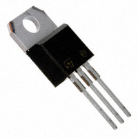
Datasheet STMicroelectronics TYN810RG — 数据表
| 制造商 | STMicroelectronics |
| 系列 | TYN410, TYN610, TYN810 |
| 零件号 | TYN810RG |

10 A标准SCR
TYNx10系列
数据表
® TYNx10 Series
10A SCR
A STANDARD Table 1: Main Features Symbol IT(RMS) VDRM/VRRM IGT Value 10 400, 600 and 800 15 Unit A V mA
G K A DESCRIPTION The TYNx10 Silicon Controlled Rectifiers is a high performance glass passivated technology. This general purpose Silicon Controlled Rectifiers is designed for power supply up to 400Hz on resistive or inductive load. K A G TO-220AB Table 2: Order Codes Part Numbers TYN410RG TYN610RG TYN810RG Marking TYN410 TYN610 TYN810 Table 3: Absolute Ratings (limiting values) Symbol Parameter IT(RMS) IT(AV) ITSM IІt dI/dt IGM PG(AV) PGM VDRM VRRM Tstg Tj TL RMS on-state current (180° conduction angle) Average on-state current (180° conduction angle) Non repetitive surge peak on-state current IІt Value for fusing Critical rate of rise of on-state current IG = 100 mA , dIG/dt = 0.1 A/µs Peak gate current Average gate power dissipation Maximum gate power Repetitive peak off-state voltage Storage junction temperature range Operating junction temperature range Maximum lead temperature for soldering during 10s at 2mm from case tp = 20 µs TYN410 TYN610 TYN810 Tj = 125°C tp = 20 µs tp = 8.3 ms tp = 10 ms tp = 10 ms Tc = 100°C Tc = 100°C Tj = 25°C Tj = 25°C Tj = 125°C Tj = 125°C Tj = 125°C Tj = 125°C Value 10 6.4 105 100 50 50 4 1 10 400 600 800 -40 to + 150 -40 to + 125 260 Unit A A A A2S A/µs A W W V °C °C February 2006 REV. 2 1/6 TYNx10 Series
Tables 4: Electrical Characteristics (Tj = 25°C, unless otherwise specified) Symbol IGT VGT VGD tgt IH IL dV/dt VTM IDRM IRRM tq VD = 12 V (D.C.) VD = VDRM IT = 100 mA IG = 1.2 x IGT Linear slope up to: VD = 67 % VDRM Gate open ITM = 20 A tp = 380 µs Tj = 25°C Tj = 110°C Tj = 110°C Test Conditions RL = 33 Tj = 110°C MAX. MAX. MIN. TYP. MAX. TYP. MIN. MAX. MAX. TYP. Value 15 1.5 0.2 2 30 50 200 1.6 10 2 70 Unit mA V V µs mA mA V/µs V µA mA µs RL = 3.3 k Gate open VD = VDRM IG = 40 mA dIG/dt = 0.5 A/µs VDRM = VRRM VD = 67 % VDRM ITM = 20 A VR = 25 V Tj = 110°C dITM/dt = 30 A/µs dVD/dt = 50 V/µs Table 5: Thermal Resistance Symbol Rth(j-c) Rth(j-a) Junction to case (D.C.) Junction to ambient Parameter Value 2.5 60 Unit °C/W °C/W Figure 1: Maximum average power dissipation versus average on-state current Figure 2: Correlation between maximum average power dissipation and maximum allowable temperature (Tamb and Tlead)
P(W)
12 = 180° Rth = 6°C/W Rth = 4°C/W Rth = 2°C/W P(W)
12 10 Tcase(°C)
Rth = 0°C/W = 120°
8 6 = 180° DC 10 8 6 100 105 110 115 120 = 90° = 60° = 30°
4
360° 4 2 2 IT(AV)(A)
0 0 1 2 3 4 5 6 7 0
8 9
0 20 40 Tamb(°C)
60 80 100 120 140 125 2/6 TYNx10 Series
Figure 3: Average on-state cur …
价格
模型线
制造商分类
- Sense & Power and Automotive Products > Thyristors (SCR) and AC Switches > Thyristors (SCR) > Standard Thyristors (SCR)