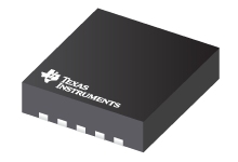
Datasheet Texas Instruments LDC1101 — 数据表
| 制造商 | Texas Instruments |
| 系列 | LDC1101 |

1.8V,高分辨率电感数字转换器
数据表
LDC1101 1.8-V High-Resolution, High-Speed Inductance-to-Digital Converter datasheet
PDF, 1.4 Mb, 修订版: D, 档案已发布: Oct 3, 2016
从文件中提取
价格
状态
| LDC1101DRCR | LDC1101DRCT | |
|---|---|---|
| Lifecycle Status | Active (Recommended for new designs) | Active (Recommended for new designs) |
| Manufacture's Sample Availability | No | Yes |
打包
| LDC1101DRCR | LDC1101DRCT | |
|---|---|---|
| N | 1 | 2 |
| Pin | 10 | 10 |
| Package Type | DRC | DRC |
| Industry STD Term | VSON | VSON |
| JEDEC Code | S-PDSO-N | S-PDSO-N |
| Package QTY | 3000 | 250 |
| Carrier | LARGE T&R | SMALL T&R |
| Device Marking | L1101 | L1101 |
| Width (mm) | 3 | 3 |
| Length (mm) | 3 | 3 |
| Thickness (mm) | .9 | .9 |
| Pitch (mm) | .5 | .5 |
| Max Height (mm) | 1 | 1 |
| Mechanical Data | 下载 | 下载 |
参数化
| Parameters / Models | LDC1101DRCR | LDC1101DRCT |
|---|---|---|
| # Input Channels | 1 | 1 |
| Active Supply Current(Typ), mA | 2 | 2 |
| Analog Supply (V), Min | 3.46 | 3.46 |
| Interface | SPI | SPI |
| L (Inductance) Resolution, Bits | 24 | 24 |
| Operating Temperature Range, C | -40 to 125 | -40 to 125 |
| Oscillation Amplitude(Max), V | 1.2 | 1.2 |
| Oscillation Amplitude(Min), V | 0.25 | 0.25 |
| Package Group | VSON | VSON |
| Package Size: mm2:W x L, PKG | 10VSON: 9 mm2: 3 x 3(VSON) | 10VSON: 9 mm2: 3 x 3(VSON) |
| Rating | Catalog | Catalog |
| Response Time(Max), 1/fsensor | 12 | 12 |
| Response Time(Min), 1/fsensor | 19 | 19 |
| Rp (Parallel Resonance Impedance) Resolution, Bits | 16 | 16 |
| Sensor Frequency, Hz | 500k - 10M | 500k - 10M |
| Sensor Rp Range(Max), Ohms | 3.93M | 3.93M |
| Sensor Rp Range(Min), Ohms | 798 | 798 |
| Stand-By Current(Typ), uA | 150 | 150 |
生态计划
| LDC1101DRCR | LDC1101DRCT | |
|---|---|---|
| RoHS | Compliant | Compliant |
应用须知
- Performing L Measurements from LDC DRDY TimingPDF, 66 Kb, 档案已发布: Nov 6, 2015
TI’s LDC1000 and LDC1101 devices measure the resonant frequency of an LC tank to determine the inductance of a sensor. Some applications require higher measurement resolution than the LDC1000 or even LDC1101 can provide. With proper configuration of the LDC, an external time measurement device can be used for improved inductance measurement resolution. - Optimizing L Measurement Resolution for the LDC161x and LDC1101PDF, 108 Kb, 档案已发布: Feb 12, 2016
- LDC1xxx LDC Target Design (Rev. A)PDF, 907 Kb, 修订版: A, 档案已发布: May 9, 2017
Texas Instruments’ Inductive-to-Digital Converter (LDC) technology can accurately measure with a wide variety of target sizes, shapes, and material composition. There are several target design guidelines to maximize the effectiveness of an LDC measurement system. This application note covers the relevant factors of target design that affect inductive sensing, and provides guide - Setting LDC1312/4, LDC1612/4, and LDC1101 Sensor Drive ConfigurationPDF, 298 Kb, 档案已发布: Apr 5, 2016
- LDC Device Selection Guide (Rev. B)PDF, 360 Kb, 修订版: B, 档案已发布: Mar 21, 2017
- EMI Considerations for Inductive SensingPDF, 151 Kb, 档案已发布: Feb 22, 2017
This application note explains various EMI reduction techniques to help improve EMI performance for TI'sInductance-to-Digital Converters (LDC). Each section details a general technique with references to otheruseful online documents. A list of relevant EMI reduction techniques is provided for specific devices withinthe LDC family of products. - Measuring Rp of an L-C Sensor for Inductive SensingPDF, 205 Kb, 档案已发布: Oct 1, 2015
When designing an application using TI’s LDC series of inductive sensors, it is necessary to know the L-C sensor’s equivalent parallel resistance RP at the sensor’s resonant frequency. The RP value changes as the target is moved; the minimum RP occurs when the metal target is closest to the sensor. The maximum RP occurs when the target is at the farthest distance. Accordingly, both values should b
模型线
系列: LDC1101 (2)
制造商分类
- Semiconductors> Sensing Products> Inductive Sensing> Inductance to Digital Converters