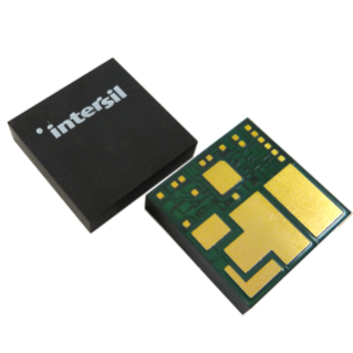
Package Outline Drawing
Y22.15x15
22 I/O 15mmx15mmx3.6mm CUSTOM HDA MODULE
Rev 2, 9/13
PIN 1 INDICATOR
C = 0.35 DATUM A
13.00 15.00 A B 1 5.00 7.30 0.10 C 2X
0.10 C 2X 13.60 В±0.15
fff
CAB TOP VIEW DATUM B
0.50 BOTTOM VIEW
1.50 3.7 MAX
0.10 C 0.10
0.10 4 17x (0.60В±0.05) 0.08 C
MAX 0.025 DETAIL B C A B
C SEATING PLANE SIDE VIEW C 3 1.00 NOTES:
1. All dimensions are in millimeters. 2. All tolerances В± 0.10mm, unless otherwise noted. 3. Represents the basic land grid pitch. 4. The total number of smaller I/O pads is 17. All 17
I/O’s are centered in a fixed row and column matrix
at 1.0mm pitch BSC. 5. Dimensioning and tolerancing per ASME Y14.5M-1994. 6. Tolerance for exposed DAP edge location dimension. 1.00
1.00 4 17x (0.60В±0.05)
1.00 TERMINAL TIP DETAIL A 3 Plastic Packages for Integrated Circuits A
B
C …
